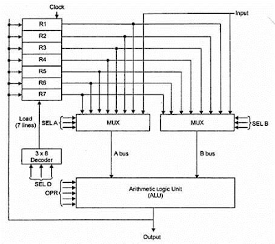
decoder & Multiplexer
In digital electronics, a binary decoder is a combinational logic circuit that converts binary information from the n coded inputs to a maximum of 2n unique outputs. They are used in a wide variety of applications, including data demultiplexing, seven segment displays, and memory address decoding.
Block Diagram Truth Table
logic diagram
Multiplexer is
a combinational circuit that has maximum of 2n data inputs, ‘n’
selection lines and single output line. One of these data inputs will be
connected to the output based on the values of selection lines.
The name “Decoder” means to translate or decode coded information from one format into another, so a binary decoder transforms “n” binary input signals into an equivalent code using 2n outputs.
Binary Decoders are another type of digital logic device that has inputs of 2-bit, 3-bit or 4-bit codes depending upon the number of data input lines, so a decoder that has a set of two or more bits will be defined as having an n-bit code, and therefore it will be possible to represent 2n possible values. Thus, a decoder generally decodes a binary value into a non-binary one by setting exactly one of its n outputs to logic “1”.
If a binary decoder receives n inputs (usually grouped as a single Binary or Boolean number) it activates one and only one of its 2n outputs based on that input with all other outputs deactivated.
An example of a 2-to-4 line decoder along with its truth table is given as:
A 2-to-4 Binary Decoders
Block Diagram Truth Table
logic diagram
3 Line to 8 Line Decoder
This decoder circuit gives 8 logic outputs for 3 inputs and has a enable pin. The circuit is designed with AND and NAND logic gates. It takes 3 binary inputs and activates one of the eight outputs. 3 to 8 line decoder circuit is also called as binary to an octal decoder.
S0
|
S1
|
S2
|
E
|
D0
|
D1
|
D2
|
D3
|
D4
|
D5
|
D6
|
D7
|
x
|
x
|
x
|
0
|
0
|
0
|
0
|
0
|
0
|
0
|
0
|
0
|
0
|
0
|
0
|
1
|
0
|
0
|
0
|
0
|
0
|
0
|
0
|
1
|
0
|
0
|
1
|
1
|
0
|
0
|
0
|
0
|
0
|
0
|
1
|
0
|
0
|
1
|
0
|
1
|
0
|
0
|
0
|
0
|
0
|
1
|
0
|
0
|
0
|
1
|
1
|
1
|
0
|
0
|
0
|
0
|
1
|
0
|
0
|
0
|
1
|
0
|
0
|
1
|
0
|
0
|
0
|
1
|
0
|
0
|
0
|
0
|
1
|
0
|
1
|
1
|
0
|
0
|
1
|
0
|
0
|
0
|
0
|
0
|
1
|
1
|
0
|
1
|
0
|
1
|
0
|
0
|
0
|
0
|
0
|
0
|
1
|
1
|
1
|
1
|
1
|
0
|
0
|
0
|
0
|
0
|
0
|
0
|
Since
there are ‘n’ selection lines, there will be 2n possible
combinations of zeros and ones. So, each combination will select only one data
input. Multiplexer is also called as Mux.
4x1 Multiplexer
4x1
Multiplexer has four data inputs I3, I2, I1 &
I0, two selection lines s1 & s0and
one output Y. The block diagram of 4x1 Multiplexer is shown in
the following figure.
One of
these 4 inputs will be connected to the output based on the combination of
inputs present at these two selection lines. Truth table of
4x1 Multiplexer is shown below.
Selection Lines
|
Output
|
|
S1
|
S0
|
Y
|
0
|
0
|
I0
|
0
|
1
|
I1
|
1
|
0
|
I2
|
1
|
1
|
I3
|
From
Truth table, we can directly write the Boolean function for
output, Y as
Y=S1′S0′I0+S1′S0I1+S1S0′I2+S1S0I3Y=S1′S0′I0+S1′S0I1+S1S0′I2+S1S0I3
We can
implement this Boolean function using Inverters, AND gates & OR gate.
The circuit diagram of 4x1 multiplexer is shown in the
following figure.


Comments
Post a Comment