Instruction Codes & Instruction Cycle
Instruction Codes
While a Program, as we all know, is, A set of instructions that specify the operations, operands, and the sequence by which processing has to occur. An instruction code is a group of bits that tells the computer to perform a specific operation part.
Operands are the objects that are manipulated and operators are the symbols that represent specific actions. For example, in the expression. 5 + x. x and 5 are operands and + is an operator. All expressions have at least one operand.
Instruction Code: Operation Code
The operation code of an instruction is a group of bits that define operations such as add, subtract, multiply, shift and compliment. The number of bits required for the operation code depends upon the total number of operations available on the computer. The operation code must consist of at least n bits for a given 2^n operations. The operation part of an instruction code specifies the operation to be performed.
Instruction Code: Register Part
The operation must be performed on the data stored in registers. An instruction code therefore specifies not only operations to be performed but also the registers where the operands(data) will be found as well as the registers where the result has to be stored.
Stored Program Organisation
The simplest way to organize a computer is to have Processor Register and instruction code with two parts. The first part specifies the operation to be performed and second specifies an address. The memory address tells where the operand in memory will be found.
Instructions are stored in one section of memory and data in another.
Instruction code has two parts
1. Opcode
2. Address
Opcode Short for Operation Code, which is the part of an instruction in machine language to specify the operation to be performed. A complete machine language instruction consists of an opcode and zero or more operands with which the specified operation is performed. Examples are “add memory location A to memory location B,” or “store the number five in memory location C.” “Add” and “Store” are the opcodes in these examples.
In memory we have Instruction and operands data.
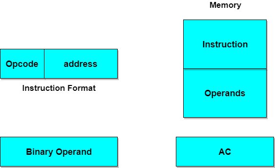
Computers with a single processor register is known as Accumulator (AC). The operation is performed with the memory operand and the content of AC.
Format of Instruction
The format of an instruction is depicted in a rectangular box symbolizing the bits of an instruction. Basic fields of an instruction format are given below:
- An operation code field that specifies the operation to be performed.
- An address field that designates the memory address or register.
- A mode field that specifies the way the operand of effective address is determined.
Computers may have instructions of different lengths containing varying number of addresses. The number of address field in the instruction format depends upon the internal organization of its registers.

Instruction Cycle
An instruction cycle, also known as fetch-decode-execute cycle is the basic operational process of a computer. This process is repeated continuously by CPU from boot up to shut down of computer.
Following are the steps that occur during an instruction cycle:
1. Fetch the Instruction
The instruction is fetched from memory address that is stored in PC(Program Counter) and stored in the instruction register IR. At the end of the fetch operation, PC is incremented by 1 and it then points to the next instruction to be executed.
2. Decode the Instruction
The instruction in the IR is executed by the decoder.
3. Read the Effective Address
If the instruction has an indirect address, the effective address is read from the memory. Otherwise operands are directly read in case of immediate operand instruction.
4. Execute the Instruction
The Control Unit passes the information in the form of control signals to the functional unit of CPU. The result generated is stored in main memory or sent to an output device.
The cycle is then repeated by fetching the next instruction. Thus in this way the instruction cycle is repeated continuously.

Adressing Modes and Instruction Cycle
The operation field of an instruction specifies the operation to be performed. This operation will be executed on some data which is stored in computer registers or the main memory. The way any operand is selected during the program execution is dependent on the addressing mode of the instruction. The purpose of using addressing modes is as follows:
- To give the programming versatility to the user.
- To reduce the number of bits in addressing field of instruction.
Types of Addressing Modes
Below we have discussed different types of addressing modes one by one:
Immediate Mode
In this mode, the operand is specified in the instruction itself. An immediate mode instruction has an operand field rather than the address field.
For example:
ADD 7, which says Add 7 to contents of accumulator. 7 is the operand here.Register Mode
In this mode the operand is stored in the register and this register is present in CPU. The instruction has the address of the Register where the operand is stored.

Register Indirect Mode
In this mode, the instruction specifies the register whose contents give us the address of operand which is in memory. Thus, the register contains the address of operand rather than the operand itself.

Direct Addressing Mode
In this mode, effective address of operand is present in instruction itself.
- Single memory reference to access data.
- No additional calculations to find the effective address of the operand.

For Example:
ADD R1, 4000 - In this the 4000 is effective address of operand.
NOTE: Effective Address is the location where operand is present.
Indirect Addressing Mode
In this, the address field of instruction gives the address where the effective address is stored in memory. This slows down the execution, as this includes multiple memory lookups to find the operand.

Common Bus System
The basic computer has 8 registers, a memory unit and a control unit. Paths must be provided to transfer data from one register to another. An efficient method for transferring data in a system is to use a Common Bus System. The output of registers and memory are connected to the common bus.
Computer Instructions
The basic computer has three instruction code formats.
The Operation code (opcode) part of the instruction contains 3 bits and remaining 12+1 bits depends upon the operation code encountered.(1 bit for mode)
The Operation code (opcode) part of the instruction contains 3 bits and remaining 12+1 bits depends upon the operation code encountered.(1 bit for mode)
There are three types of formats:
1. Memory Reference Instruction
It uses
12 bits to specify the address and 1 bit to specify the addressing mode (I). I is equal to 0for direct address and 1 for indirect address.range:
opcode 000-110
2. Register Reference Instruction
These instructions are recognized by the opcode
111 with a 0 in the left most bit of instruction. The other 12 bits specify the operation to be executed.mode 0 and opcode range :111
3. Input-Output Instruction
These instructions are recognized by the operation code
mode 1 opcode 111
111 with a 1 in the left most bit of instruction. The remaining 12 bits are used to specify the input-output operation.mode 1 opcode 111


Brilliant ansr
ReplyDeleteAn instruction code is the fundamental building block of computer programs, defining the actions the computer must perform. It is composed of operation codes and other parts that provide necessary details for the execution of these operations. ejeas q8 intercom
ReplyDelete