Registers Transfer and Micro Operation
Registers in Computer Architecture
Register is a very fast computer memory, used to store data/instruction in-execution.
A Register is a group of flip-flops with each flip-flop capable of storing one bit of information. An n-bitregister has a group of n flip-flops and is capable of storing binary information of n-bits.
A register consists of a group of flip-flops and gates. The flip-flops hold the binary information and gates control when and how new information is transferred into a register. Various types of registers are available commercially. The simplest register is one that consists of only flip-flops with no external gates.
These days registers are also implemented as a register file.
Loading the Registers
The transfer of new information into a register is referred to as loading the register. If all the bits of register are loaded simultaneously with a common clock pulse than the loading is said to be done in parallel.
Register Transfer Language
The symbolic notation used to describe the micro-operation transfers amongst registers is called Register transfer language.
The term register transfer means the availability of hardware logic circuits that can perform a stated micro-operation and transfer the result of the operation to the same or another register.
The word language is borrowed from programmers who apply this term to programming languages. This programming language is a procedure for writing symbols to specify a given computational process.
Following are some commonly used registers:
- Accumulator: This is the most common register, used to store data taken out from the memory.An accumulator is a register for short-term, intermediate storage of arithmetic and logic data in a computer's CPU (central processing unit).
- General Purpose Registers: This is used to store data intermediate results during program execution. It can be accessed via assembly programming.General purpose registers in 8086 microprocessor. General purpose registers are used to store temporary data within the microprocessor. ...
- Special Purpose Registers: Users do not access these registers. These registers are for Computer system,
- MAR: Memory Address Register are those registers that holds the address for memory unit.
- MBR: Memory Buffer Register stores instruction and data received from the memory and sent from the memory.
- PC: Program Counter points to the next instruction to be executed.
- IR: Instruction Register holds the instruction to be executed.
Registers are the most important components of CPU. Each register performs a specific function. A brief description of most important CPU's registers and their functions are given below:
1. Memory Address Register (MAR):
This register holds the address of memory where CPU wants to read or write data. When CPU wants to store some data in the memory or reads the data from the memory, it places the address of the required memory location in the MAR.
2. Memory Buffer Register (MBR):
This register holds the contents of data or instruction read from, or written in memory. The contents of instruction placed in this register are transferred to the Instruction Register, while the contents of data are transferred to the accumulator or I/O register.
In other words you can say that this register is used to store data/instruction coming from the memory or going to the memory.
3. I/O Address Register (I/O AR):
I/O Address register is used to specify the address of a particular I/O device.
I/O Address register is used to specify the address of a particular I/O device.
4. I/O Buffer Register (I/O I3R):
I/O Buffer Register is used for exchanging data between the I/O module and the processor.
5. Program Counter (PC)
Program Counter register is also known as Instruction Pointer Register. This register is used to store the address of the next instruction to be fetched for execution. When the instruction is fetched, the value of IP is incremented. Thus this register always points or holds the address of next instruction to be fetched.
6. Instruction Register (IR):
Once an instruction is fetched from main memory, it is stored in the Instruction Register. The control unit takes instruction from this register, decodes and executes it by sending signals to the appropriate component of computer to carry out the task.
7. Accumulator Register:
The accumulator register is located inside the ALU, It is used during arithmetic & logical operations of ALU. The control unit stores data values fetched from main memory in the accumulator for arithmetic or logical operation. This register holds the initial data to be operated upon, the intermediate results, and the final result of operation. The final result is transferred to main memory through MBR.
Register Transfer
Information transferred from one register to another is designated in symbolic form by means of replacement operator.
R2 ← R1
It denotes the transfer of the data from register R1 into R2.
Normally we want the transfer to occur only in predetermined control condition. This can be shown by following if-then statement: if (P=1) then (R2 ← R1)
Here
P is a control signal generated in the control section.Control Function
A control function is a Boolean variable that is equal to 1 or 0. The control function is shown as:
P: R2 ← R1
The control condition is terminated with a colon. It shows that transfer operation can be executed only if P=1.
Micro-Operations
The operations executed on data stored in registers are called micro-operations. A micro-operation is an elementary operation performed on the information stored in one or more registers.
Example: Shift, count, clear and load.
Types of Micro-Operations
The micro-operations in digital computers are of 4 types:
- Register transfer micro-operations transfer binary information from one register to another.
- Arithmetic micro-operations perform arithmetic operations on numeric data stored in registers.
- Logic micro-operations perform bit manipulation operation on non-numeric data stored in registers.
- Shift micro-operations perform shift micro-operations performed on data.
Arithmetic Micro-Operations
Some of the basic micro-operations are addition, subtraction, increment and decrement.
Add Micro-Operation
It is defined by the following statement:
R3 → R1 + R2
The above statement instructs the data or contents of register R1 to be added to data or content of register R2 and the sum should be transferred to register R3.
Subtract Micro-Operation
Let us again take an example:
R3 → R1 + R2' + 1
In subtract micro-operation, instead of using minus operator we take 1's compliment and add 1 to the register which gets subtracted, i.e R1 - R2 is equivalent to R3 → R1 + R2' + 1
Increment/Decrement Micro-Operation
Increment and decrement micro-operations are generally performed by adding and subtracting 1 to and from the register respectively.
R1 → R1 + 1
R1 → R1 – 1
| Symbolic Designation | Description |
|---|---|
| R3 ← R1 + R2 | Contents of R1+R2 transferred to R3. |
| R3 ← R1 - R2 | Contents of R1-R2 transferred to R3. |
| R2 ← (R2)' | Compliment the contents of R2. |
| R2 ← (R2)' + 1 | 2's compliment the contents of R2. |
| R3 ← R1 + (R2)' + 1 | R1 + the 2's compliment of R2 (subtraction). |
| R1 ← R1 + 1 | Increment the contents of R1 by 1. |
| R1 ← R1 - 1 | Decrement the contents of R1 by 1. |
Logic Micro-Operations
These are binary micro-operations performed on the bits stored in the registers. These operations consider each bit separately and treat them as binary variables.
Let us consider the X-OR micro-operation with the contents of two registers R1 and R2.
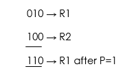
P: R1 ← R1 X-OR R2
In the above statement we have also included a Control Function.
Assume that each register has 3 bits. Let the content of R1 be 010 and R2 be 100. The X-OR micro-operation will be:

Shift Micro-Operations
These are used for serial transfer of data. That means we can shift the contents of the register to the left or right. In the shift left operation the serial input transfers a bit to the right most position and in shift right operation the serial input transfers a bit to the left most position.
There are three types of shifts as follows:
a) Logical Shift
It transfers 0 through the serial input. The symbol "shl" is used for logical shift left and "shr" is used for logical shift right.
R1 ← she R1
R1 ← she R1
The register symbol must be same on both sides of arrows.
example logical left shift 1011
0110 zero will be added at end.
b) Circular Shift
This circulates or rotates the bits of register around the two ends without any loss of data or contents. In this, the serial output of the shift register is connected to its serial input. "cil" and "cir" is used for circular shift left and right respectively.
example circular left shift R<- Cirl R a1,a2,a3,a4 ans a2,a3,a4,a1
c) Arithmetic Shift
This shifts a signed binary number to left or right. An arithmetic shift left multiplies a signed binary number by 2 and shift left divides the number by 2. Arithmetic shift micro-operation leaves the sign bit unchanged because the signed number remains same when it is multiplied or divided by 2.
example a1,a2,a3,a4
a2,a3,a4,0
a1=a2,
in right shift
a1,a2,a3,a4
a1,a1,a2,a3
example a1,a2,a3,a4
a2,a3,a4,0
a1=a2,
in right shift
a1,a2,a3,a4
a1,a1,a2,a3
Arithmetic Logical Unit
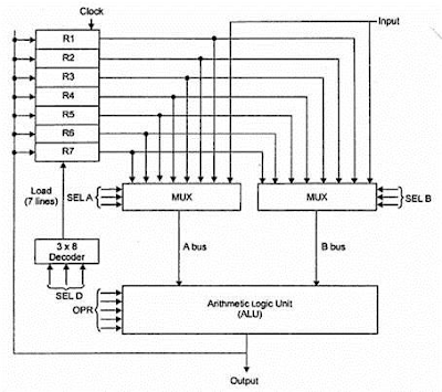
Instead of having individual registers performing the micro-operations, computer system provides a number of registers connected to a common unit called as Arithmetic Logical Unit (ALU). ALU is the main and one of the most important unit inisde CPU of computer. All the logical and mathematical operations of computer are performed here. The contents of specific register is placed in the in the input of ALU. ALU performs the given operation and then transfer it to the destination register.


Comments
Post a Comment